Biomedical device
ecg-device
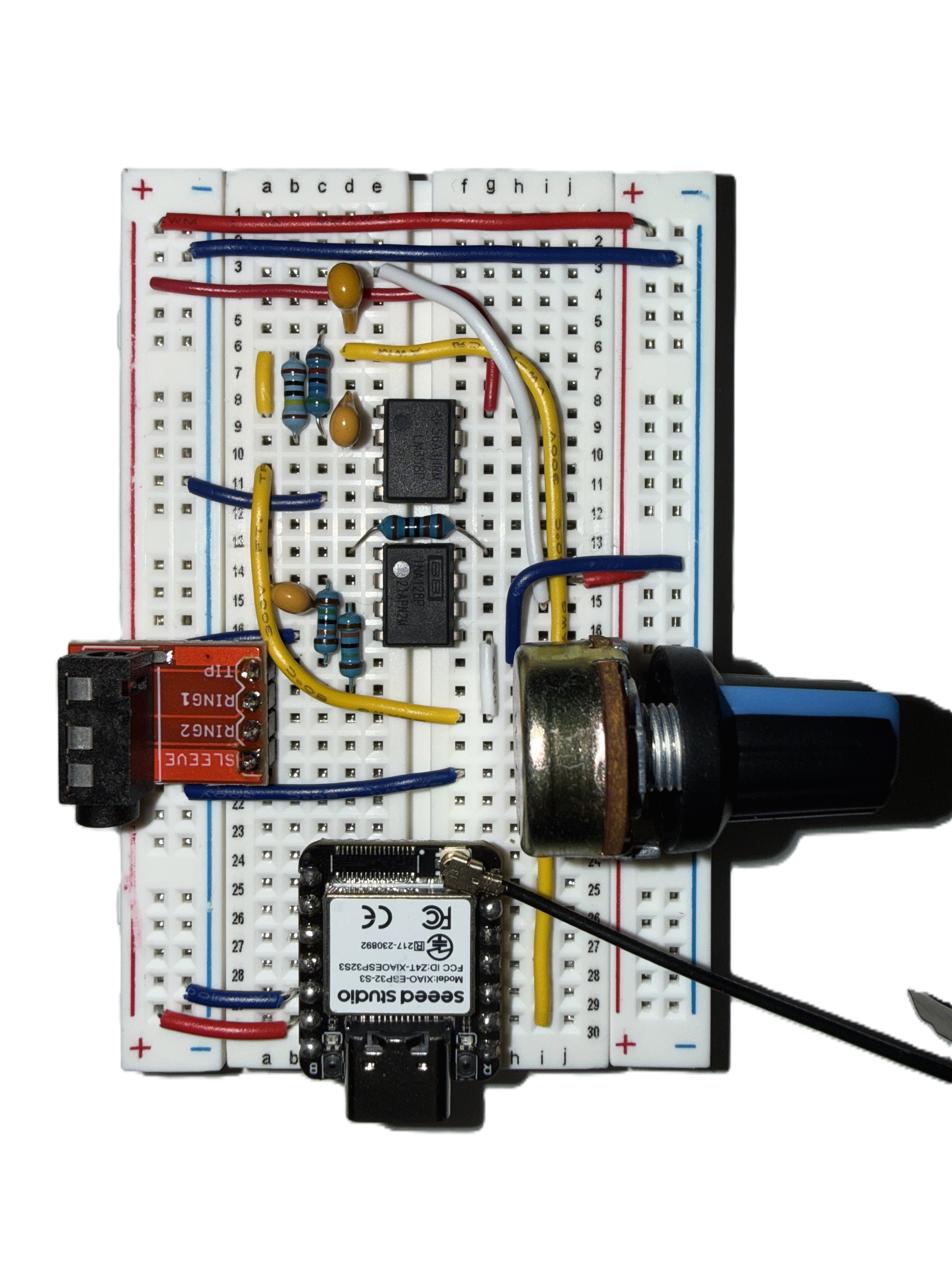
A breadboard ECG prototype (for now).
Project preview
Breadboard prototype
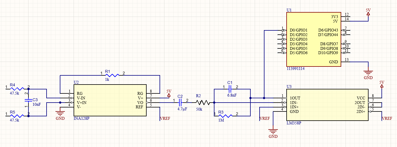
This is my first biomedical device project and my first time converting a physiological signal into a functioning hardware system. The prototype acquires an ECG signal through electrodes, amplifies it in two stages, filters it, and sends the adjusted signal to a seeed studio XIAO ESP32-S3 for analog-to-digital conversion and serial plotting.
At the input, two matched 47.5 kΩ resistors and a 10 nF capacitor form a differential low-pass filter with a nominal cutoff frequency of approximately 168 Hz.
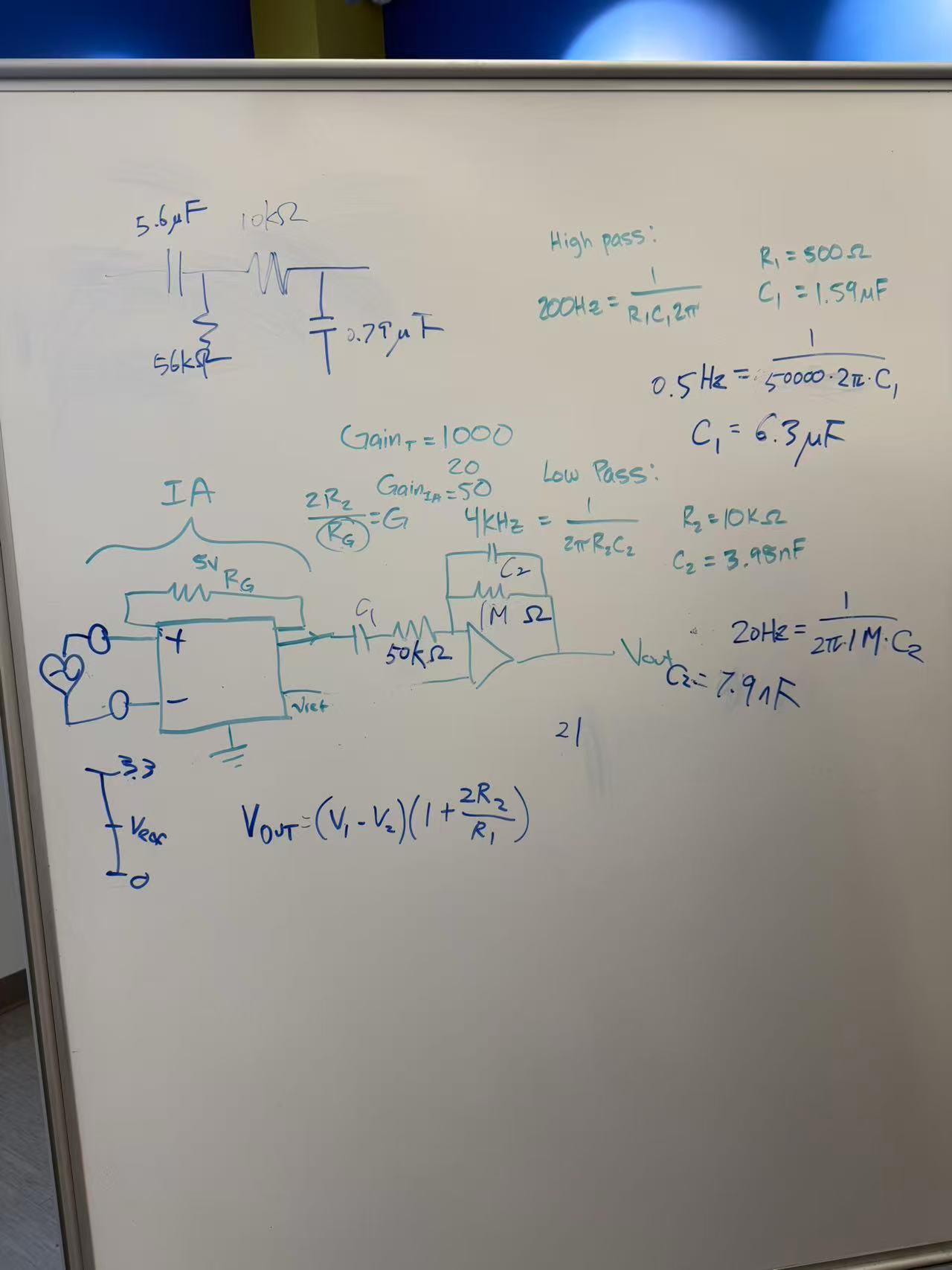
The first stage of amplification uses an INA128P instrumentation amplifier with the 1 kΩ gain-setting resistor producing a gain of 51. A reference voltage shifts the amplifier outputs around a mid-supply baseline rather than ground.
The second stage uses an LM358P operational amplifier as an active inverting band-pass filter. The 4.7 µF input capacitor and 50 kΩ resistor create a nominal 0.68 Hz high-pass cutoff. The 1 MΩ feedback resistor provides a gain magnitude of 20, and the parallel 6.8 nF capacitor creates a 23.4 Hz low-pass filter. Together, the two amplifier stages produce a gain magnitude of 1,020.
Next: a custom PCB
Before moving to a custom PCB, I would like to address the current design limitations:
- High first-stage gain before DC blocking: Motion artifacts and electrode offsets can saturate the INA128 before the 0.68 Hz high-pass filter.
- High total gain (≈1,020×): Large artifacts can drive the output into the supply rails.
- Narrow bandwidth (≈0.68–23 Hz): This range is usable, but it attenuates some ECG morphology, including higher-frequency QRS content.
- First-order filtering only: Second- or fourth-order filters would reject unwanted frequencies more effectively.
- No 50/60 Hz rejection: A digital notch filter could improve suppression of power-line interference.
- No right-leg drive: Common-mode interference picked up by the body is not actively reduced.
- INA128 and LM358 limitations at 5 V: Their input and output ranges are restricted near the supply rails. Modern rail-to-rail, low-noise amplifiers or an integrated ECG front end would provide better performance.